
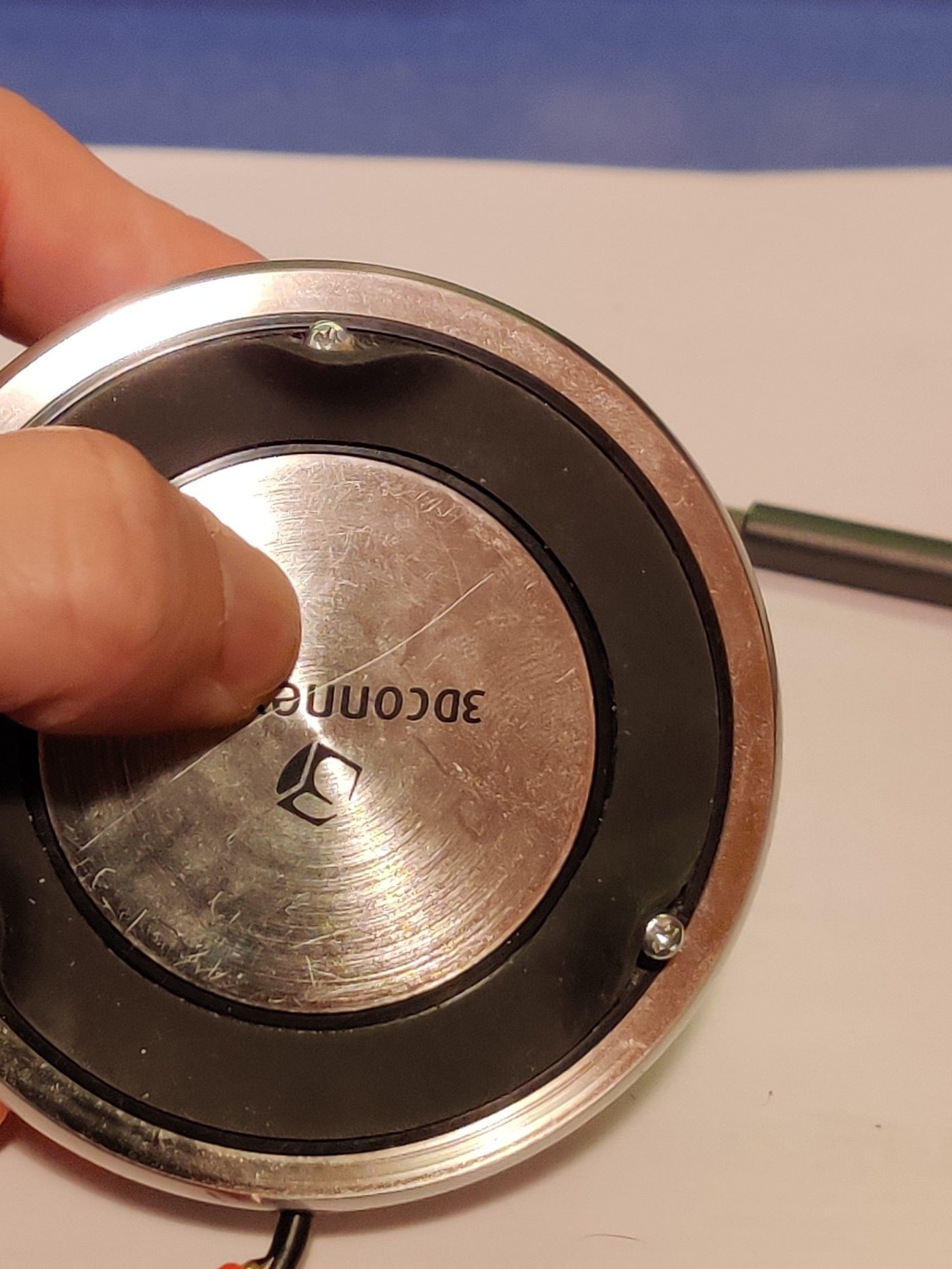
A broken 3D Connexion SpaceNavigator has fallen into my hands. I would like to know what makes it “tick” to see If I canfix it. At the end of the day, it’s just a 6 degree of freedom joystick, but to fit in this package it has some clever tricks.
To start dissasemby, three screws are hidden under the rubber base. If you do not want to tear the whole base, one of them is opposite the cable, the remaining are 120º apart
When separating the base be carefull as the cable is connected to the bottom PCB. Two screws (not shown in the image) have to be removed as to disconnect the bottom PCB to the joystick’s PCB. Once the screws are removed, it’s a matter of pulling.

The joystick can be separated from its base unscrewing the screws closest to the center. The remaining four screws can be left in place

There are also tree screws under the top cover of the joystick. A plastic tool can make this task easy.

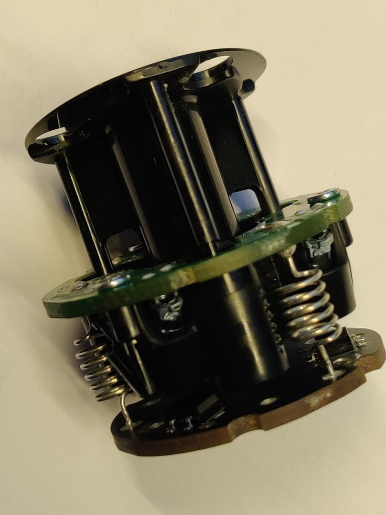
Once the screws are removed the whole joystick assembly can be removed. As you can see, there are two PCB, on the top one, there are 6 LEDs and in the bottom there are tree PSD’s. From what I’ve seen, in previous revisions of this product, each LED had a matching PSD, so there has been a very clever cost reduction in this revision
Notice also the extra thick PCBs, probable they are only two sided, but they need to be this thick because they are using self tapping screws to fix plastic parts into them


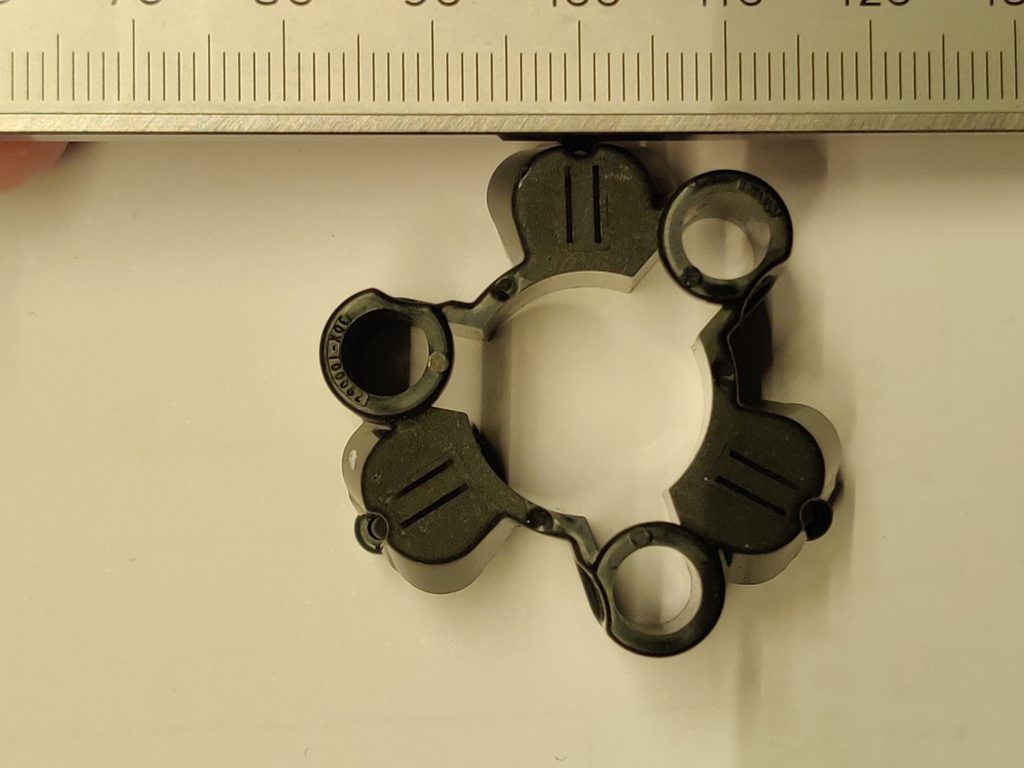
A “mask” over the IR Led’s ensures the PSD only receive a line of light per LED. As the PSD are one-dimensional, this will provide a single reference to the controller.

Power is sent to the top PCB via the springs. I would imagine that two LED cannot shine light at the same time on one PSD an therefore the have to be conmuted.


I would have figured that three LED would run in parallel with the other three with a common ground and they would be conmuted, but I was wrong. The circuit is as follows:
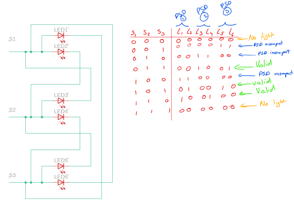
The PSD’s are an they keystone of this product. I believe they are Hamamatsu S7105-05 (They could also be S4583-04 but theese have a smaller detection size). Each of theese tree units can provide signals to locate a beam of light in a strip that runs through its center. Due to the aforementioned LED confirguration, each PSD can take two degrees of freedom to compute the 3d position of the joystick.

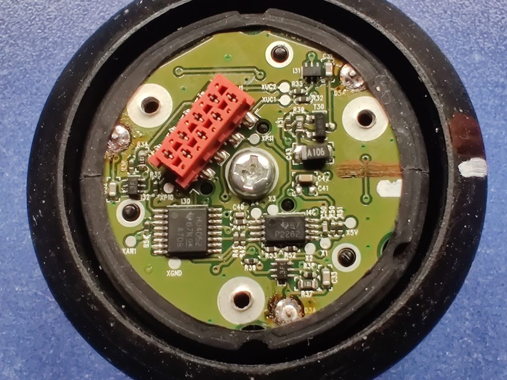
These PSD output a current based on light intensity, so I would be expecting to find some sort of transimpedance amplifier. Instead, the main ICs on this board are a HJ 4052 (link)and a P2262 (link).


Super clever product, with cost in mind